Altsickeness
Quad Addict
Oh and tape didnt seem to help.
I usually prefer to DIY my frames because of the repairability and customizability. No waiting on parts to arrive hahaha. I can make 4 new arms with a little stick of wood (I have a 5 gallon bucket full of arms basically all I have to do is cut an angle on the end and drillholes)Well... Im getting sick of this thing. View attachment 1590 Another arm broke. I dont know... Maybe acro in 20mph wind wasnt such a good idea.
I don't think it's the wind, it's that extra 1500 grams of paint you added (JJ)Well... Im getting sick of this thing. View attachment 1590 Another arm broke. I dont know... Maybe acro in 20mph wind wasnt such a good idea.
That has got to be one of the spiffiest AMR build I've seen hahahaa.I don't think it's the wind, it's that extra 1500 grams of paint you added (JJ)
http://www.ebay.com/itm/ZMR-250-250...956078?hash=item3abe214aee:g:yv4AAOSw3ydVny62
I don't think it's the wind, it's that extra 1500 grams of paint you added (JJ)
http://www.ebay.com/itm/ZMR-250-250...956078?hash=item3abe214aee:g:yv4AAOSw3ydVny62
I don't think it's the wind, it's that extra 1500 grams of paint you added (JJ)
http://www.ebay.com/itm/ZMR-250-250...956078?hash=item3abe214aee:g:yv4AAOSw3ydVny62
")
Yep, a BEC is a battery eliminator circuit, steps down the voltage so that you don't a second lower voltage battery.Guys, I have a newb question. If Im looking at a quad frame and it says it comes with a BEC board is that basically a power distribution board that has a stepdown relay from 12 to 5volts?
Probably similar to this. I've got the Diatone centre plate. The ESC's go directly to the plate so it saves a lot of wiring, and it has 5V and 12V outputs.Yep, a BEC is a battery eliminator circuit, steps down the voltage so that you don't a second lower voltage battery.
")
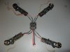
It's really quite simple, this pic should explain. The BEC's are fed a full 14.1 V from the PDB. They drop it down to 5 V which are sent to the FCB via the 3 wire servo cables you see (red = positive, brown = negative, yellow/white = signal. Note that only BEC 1 in the top left corner has all 3 pos, neg & signal wires that are input in M1 of your FCB, the other 3 leads only need to be signal and ground wire as the FCB already has power from #1. That's itOld blue dropped out of the sky. No power to the escs. I need a little help undestanding how escs work exactly because immgoing to try and fully bypass the pcb. Ive been looking at escs for a new build and lots of them have 3 wires to the motor on one side and 4 wires on the other.
I have this on my racer 250. Three wires into the esc and three wires out to the motor. http://www.banggood.com/Eachine-Racer-250-Drone-Spare-Part-Simonk-12A-ESC-2-4S-p-1014103.html
But most of the escs i see have 4 wires coming out the one side. Im wondeing exactly were thise wires go. Like this: http://www.banggood.com/Emax-Simonk...-40A-ESC-For-Quadcopter-QAV-250-p-918126.html
Im circling around this trying to understand BEC and trying to understand the power flow from the fcb to the escs and to the motor and what BEC does and why my Racer 250 doesnt have the extra wire. Can someone help me understand it? Ive watched several videos on this but none seem to explain exactly how it works so I can visualize and understand it. All the vids so far are general information but no detail.
Old blue dropped out of the sky. No power to the escs. I need a little help undestanding how escs work exactly because immgoing to try and fully bypass the pcb. Ive been looking at escs for a new build and lots of them have 3 wires to the motor on one side and 4 wires on the other.
I have this on my racer 250. Three wires into the esc and three wires out to the motor. http://www.banggood.com/Eachine-Racer-250-Drone-Spare-Part-Simonk-12A-ESC-2-4S-p-1014103.html
But most of the escs i see have 4 wires coming out the one side. Im wondeing exactly were thise wires go. Like this: http://www.banggood.com/Emax-Simonk...-40A-ESC-For-Quadcopter-QAV-250-p-918126.html
Im circling around this trying to understand BEC and trying to understand the power flow from the fcb to the escs and to the motor and what BEC does and why my Racer 250 doesnt have the extra wire.
That is specifically made to mate to their PCB, the yellow is probably just the signal wire, do you have a solder pad on the PCB with an 'S' on it? You notice there is no mention of a BEC on the listing, which means it's on the PCB. I'd imagine you could use one of these optos.Three wires into the esc and three wires out to the motor

Thank you! That seems pretty easy. From position one bec inside the esc the fcb gets its 5vt power and ground. It looks like you just cut off and seal up the other 3?It's really quite simple, this pic should explain. The BEC's are fed a full 14.1 V from the PDB. They drop it down to 5 V which are sent to the FCB via the 3 wire servo cables you see (red = positive, brown = negative, yellow/white = signal. Note that only BEC 1 in the top left corner has all 3 pos, neg & signal wires that are input in M1 of your FCB, the other 3 leads only need to be signal and ground wire as the FCB already has power from #1. That's it
That is specifically made to mate to their PCB, the yellow is probably just the signal wire, do you have a solder pad on the PCB with an 'S' on it? You notice there is no mention of a BEC on the listing, which means it's on the PCB. I'd imagine you could use one of these optos.
On this one the white is the signal wire and the black is the ground, which appears to be not needed in your case.
If you choose to use BG 2-4S ESCs and bypass the PCB you'll need to get a standalone UBEC.
http://www.amazon.com/DLFPV®-4-Axis-Carbon-Racing-Quadcopter/dp/B01DBOH16W?ie=UTF8&psc=1&redirect=true&ref_=ox_sc_act_title_1&smid=A3D72ERSO97IXM
http://www.amazon.com/ARRIS®-Naze32-Controller-Distribution-Multicopter/dp/B00UFK8VJ2?ie=UTF8&psc=1&redirect=true&ref_=ox_sc_act_title_2&smid=A37EFSP4QP9HL5
http://www.amazon.com/Emax-RS2205-R...ue&ref_=ox_sc_act_title_3&smid=A2YGVOB7APVMLY
http://www.amazon.com/Emax-RS2205-R...ue&ref_=ox_sc_act_title_3&smid=A2YGVOB7APVMLY
Will all these items work together? Am I missing anything?
I plan on flying with 3s 1500mah batteries for now because I have lots of them and 5040 and 5045BN props because I have lots of those as well.