Noob esc question

2manyhobyz

New Member
I'm an old nitro RC'r and just got an interest in mini quads.
Just to try out fpv without spending a fortune, and knowing almost nothing electronic, I picked up a Wizzard x 220 and was enjoying it very much, then I decided to add a buzzer and batt monitor.....bad decision.
I ended up toasting the pcb.
I was able to order and replace it, but in the process, I believe I cooked an esc.
I now realize my shoddy soldering resulted in one pos esc lead contacting the adjacent main batt lead when soldering to the pdb pads.
Question is, since I checked continuity on another (extra) pdb I had, and there was continuity between all pos esc pads and the main batt pad, does it even matter that an esc contacted the batt lead.
I assume it does since that particular esc, or motor doesnt work and I think the esc's use 5v ?,
I have a replacement set of littlebees to install, but those have an additional ground wire with the signal wire that the original esc doesn't have, also, the esc power and ground wires are much smaller than the original ones.
I have watched youtube vids and read till my eyes are crossed and I'm still not sure I know enough to feel confident in changing the esc's.
I'd be most grateful for any guidance anyone's willing to offer.
Thanks, Rod
Can you post a picture?
 
there was continuity between all pos esc pads and the main batt pad, does it even matter that an esc contacted the batt lead.
I assume it does since that particular esc, or motor doesnt work and I think the esc's use 5v?,
No, the ESCs will use main battery voltage and all of them are paralleled.

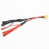
Here is the style of power distribution harness that I use on my tricopter. Note mine only has 3 pos and neg leads.

Tricopter harness _57.JPG
 
first, the esc uses the battery voltage, not 5v. The signal wire is another story but you did not say you crossed that pad. Crossing the pos on an esc to the pos on a battery is exactly what your power distribution board does and is probably not why your motor does not work. Easy enough to check, use a volt meter on an esc pad with the battery connected. it will read the battery voltage.

second, the extra ground wire on the little be is for calibrating the esc. You can cut it off, do not need it. You can calibrate your esc via cleanflight/betaflight/raceflight/baseflight. (all same program pretty much) Connect your quad, go to motor tab, put master to highest setting and plug in battery. After the beeping stops, click, dont slide, the master bar to the bottom. After beeping stops, unplug the quad from battery and computer. Done. All esc calibrated at the same time. Can do them one at a time if you like. Some people like taking the long way home.

Personally, i would have bought the bullet series esc from Emax. They are about 1/3rd the size of the littlebee. Can put them anywhere.

Connecting the esc is easy. Three wires from the esc. ground, positive to power distribution board and signal wire to flight controller unless you are using an integrated PDB with the base plate of the quad. Then it will have pad for the signal wire marked "s". Three wires from the motor to the esc. Only one that matters is the center wire connected to the center pad. The outer two wires determine the direction of the motor. DOES NOT MATTER if you get them wrong. Can change the direction of the motor in the BLheli program via software. So wire them as you see fit.

About soldering. Use a small tip and clean up your soldering with a cotton swab and alcohol afterwards to clean up the flux. The flux can bridge a connection if you dont. Personally, i use a stand with a lighted magnifying glass and two arms to hold stuff. The best time to inspect your soldering job and re-solder if necessary is BEFORE you put the quad back together.

About integrated power distribution boards with the base of the quad. It probably has a micro connector to connect the signal wires from the esc to the flight controller. If it does, some of them were set up for open pilot and some were set up for betaflight. The motor numbering is different. On the openpilot boards, the motors are numbered starting from the top left, 1234. In clanflight they are numbered starting from top left 4213. Why? Have to ask the developers. Maybe they just wanted to be different and WE have to pay the price as neither bothers to tell you that little fact. If your quad flips on takeoff, check the motor numbering.

personally, i do not like integrated power distribution boards. Hard to track down a short and too many things to keep track of like capacitors and voltage regulators. But my first 250 quad has one and it still flies after replacing just about everything else. So not going to say less dependable.

Good luck. Quads involve countess hours sifting through rubbish on the web for answers you just flat out do not get sometimes. No reliable information, especially when you have a problem. That is part of the reason i like my PDB separate from the quad. Easy to replace to eliminate as part of tracking down a problem. The gear you buy will come with a pin out map but ZERO explanation of what goes where and how. Trial and error is how you learn because most of the time people will not answer your questions on web sites or those that do will not have enough experience to answer it correctly. It is part of the journey and why all of us will make the same mistakes over and over. We do not communicate and the techno geeks who write the software and make the hardware cant be bothered to write down why they did this, what its for and how to use it. Opensource means you are on your own pretty much.
 
rosco11, I sincerely thank you for your time / effort to offer such a thorough explanation to help me resolve this.
The type of details you include are priceless for the electronically challenged type people such as myself.
The most elementary aspects can be the most elusive because many newb issues are just nailing down the fundimentals.
Example, while setting up my quad in Betaflight the 1st time, it took me 3 days to be certain if and when the battery should be connected during the process.
These things are so ingrained for seasoned pilots, that it's easy to overlook, even when making a true and honest effort to film how to videos ect.

I do have a separate pdb and fc, thank heaven.
And have learned to calibrate the esc's via Betaflight as you described.
I was tempted to take the easiest route and just unsolder my old esc's and slip in the new ones, but, I can't stand to look at my previous shoddy pdb soldering any longer, so, now that I know to remove the extra ground wire, after I check the voltage and for sure determine it's a faulty esc, I will take the time to redo all the pdb solder pad connections.

Now, I must further display my lacking knowledge, if I may impose once more,
would you mind to advise as to the proper setting for my multimeter in checking the esc current?
I will try to include a pic of the actual meter I have.
Again, thank you so very much for your assistance!
 

Attachments

  • 1495379392315-2027161068.jpg
    1495379392315-2027161068.jpg
    592.4 KB · Views: 3
Hallelujah! !!!!!
Why oh why can I never try the simplest solutions first!
My default thinking is that I could never have a small problem.
Just before stripping all my esc's for replacement, as rosco11 suggested, I attempted to calibrate the esc's again.
I hadn't done that since replacing the pdb, and what d ya know, problem solved! !!!

Many thanks rosco11!!!
 
Go back and check your solder joints again before you put it together. Also go over them with alcohol and clean up the flux.

As well be aware than carbon fiber will conduct. best to insulate your wires and connections from it. Personally, i run a strip of electrical tape down the whole arm under the esc and wiring, they are the most vulnerable to damage from tree branches.

Another little tip you will not find written anywhere, NEVER use metal standoffs on any of your electronic gear for the above reason. nylon is your friend.

Glad you found it useful.
 
Back
Top