Newbie Drone build help needed

I don't know were you found that relic but for $5 this one is very nice:
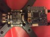
I bought it after guidence in this very thread. You can see my current specs on page one. I will use a board with 40A Racestar ESC's. Is this https://www.ebay.co.uk/itm/MATEK-Sy...631616?hash=item2884cba9c0:g:PusAAOSw9g1cRahw a good choice or are there other options I should consider? I don't want to buy too many of these things. =)
 
Okay since I don't want to be giving bad advice I did a re-read of this thread lol. The PDB renov8tr suggested was this:
Since you are using 40 amp escs this makes more sense because of the amps.
 
Okay since I don't want to be giving bad advice I did a re-read of this thread lol. The PDB renov8tr suggested was this:
Since you are using 40 amp escs this makes more sense because of the amps.

Thanks for the extra effort. I ordered one right away.
 
All good. I'm actually at work, bored lol so it's like I'm getting paid for this. All I ask is that you post some flight videos once you get her up and flying. We love flight videos here lol!
 
All good. I'm actually at work, bored lol so it's like I'm getting paid for this. All I ask is that you post some flight videos once you get her up and flying. We love flight videos here lol!

Good man! I surely will, when I get there. But now I will need to wait 10-14 days for this thing and some nuts and bols etc. Watch this space!
 
In the meanwhile. What kind of charger should I buy for the battery? Just realized I've not bought one yet. I have this battery. https://www.ebay.co.uk/itm/TATTU-1800mAh-14-8V-45C-90C-4S-Lipo-Batteria-Con-XT60-Spina-Per-RC-Fuco-Aereo/283157716018?ssPageName=STRK:MEBIDX:IT&_trksid=p2057872.m2749.l2649
Generally what you're looking for is a balance charger. The things that will vary from one to the other are number of cells they support and max wattage (ultimately limits max charge amperage you can put through it) and if they include a transformer to hook into the wall (AC->DC). Generally speaking we only charge at 1C (1hr to charge at this rate) and means basically take capacity in Amp Hours and use that as your max amp values, if 1.8Ah battery charge at 1.8A at max to keep it safe. If you end up getting into parallel charging (bit more advanced need things to be balanced to start or can start a fire), then you may end up with say two batteries and 3.6A max charge or say you want to get to the field fast and don't give a damn about your batteries you might charge at this 2C rate for your batteries (honestly exaggerating a bit 2C still isn't that bad for most high performance cells, but say 10C is way overkill). Anyway once you know your charge rate can multiply by the peak voltage to get the max *wattage* you care about (say 4S * 4.2V = 16.8V then multiply that by charge rate in Amps say 1.8A then have 30.24W as the needed power to charge, chargers will run cooler and better if they are way above this but lowest I've really seen is around 50W anyhow.

iMax B6 is a trusted one I have a clone of it and also works well, the main charger I use now is a "Keenstone AR400" pretty sure this one isn't available anymore but they have some upgraded replacements, for that one I got a separate AC->DC since it can do up to 500W and I use it for charging my esk8 batteries which overheat my B6 clone.

---

Edit another way to look at the wattage is take your battery max voltage and divide by the charger max wattage and can get max current you could charge with before overheating the charger (will typically shut itself down but not good to do), if I have a 500W charger and a 50V battery I can charge at 500W/50V = 10A at peak (really a little less cause of other losses, but close to this probably 9.6A, but this is likely more than the battery can handle unless it is a 10Ah battery)
 
Last edited:
Hi gurus! I'm continuing the build now (not moving fast here). I feel I need to check details to make sure I don't do stupid things. I want to understand if this is the best way to turn the circut boards and if the minimal space between them is a good idea, or should I have more space in between them (which I can)? Related to that, there isn't anything alse to go on that stack, right? Last. I don't need to use any grommets as I use plastic to hold the boards, right? I don't see how such could even fit. Thanks
 

Attachments

  • p1.jpg
    p1.jpg
    248.9 KB · Views: 7
  • p2.jpg
    p2.jpg
    373.4 KB · Views: 7
  • p3.jpg
    p3.jpg
    195.7 KB · Views: 8
Hi gurus! I'm continuing the build now (not moving fast here). I feel I need to check details to make sure I don't do stupid things. I want to understand if this is the best way to turn the circut boards and if the minimal space between them is a good idea, or should I have more space in between them (which I can)? Related to that, there isn't anything alse to go on that stack, right? Last. I don't need to use any grommets as I use plastic to hold the boards, right? I don't see how such could even fit. Thanks

You typically won't use rubber grommets with nylon standoffs, but the idea is to use them to isolate the FC and other components from the frame so they aren't having to filter out all the vibrations from the motors and just get the actual orientation changes of the quad itself. Usually people will "soft mount" with long enough screws to go through all the boards in the stack and then use rubber grommets and or spacers in between the boards, you could try grommets on the bottom layer with the standoffs but think atypical.

I'd also add a bit more space between boards if you can will help keep interference between the boards to a minimum and allow both good airflow for heat dissipation just be sure no metal is touching the carbon frame.

Thank you! I have longer bolts so I can build a stack like that with grommets...I think. This fit will into my amateur thoughts, so thanks for confirming. I'll definately add some more space between the boards.
 
Last edited:
Hi! I'm about to solder my ESC to the connections to the PDB but is unsure regarding the cables. There seem to be two thin and twiested Signal cables in the middle of the ESC with a black plastic connector at the end. Is one, either the red or the orange cable, ground? Should I cut to remove one of them?
What to do? Thanks in advance!
 

Attachments

  • esc connection.jpg
    esc connection.jpg
    264.8 KB · Views: 4
Yep cut the connector off.

The orange is your signal wire, solder it into your fcb for the corresponding motor. The red is actually a ground wire, you can solder it into any ground on pcb or fcb.

Some people just remove the ground wire altogether it doesn't seem necessary lol.
 
FlySky FS-i6 2.4G 6CH AFHDS RC Radio Transmitter With FS-iA6 Receiver
Wrong one, older tech. Get the X with this smaller, lighter, newer RX.

X6B i-BUS Specifications:
Brand Name: Flysky
Item: X6B i-BUS Receiver
Channels: 6(PWM), 8(PPM), 18(i-BUS)
 
Hi experts! I'm clearly going to need step-by-step advice on what to do here. I've now connected the engines and ESC's to the PDB. What do I do next? Should I try flashing my Omnibus omnibus f4 v5 with the latest firmware (I've installed Betaflight Win 10, STM driver and downloaded BLHeliSuite32_32710)? ...or can I do more building first? If so, which things in which order? Humble thanks in advance!
 

Attachments

  • 20200306_193240829_iOS.jpg
    20200306_193240829_iOS.jpg
    347.1 KB · Views: 9
Don't worry about the firmware right now, it'll already be loaded with a fairly new version of Betaflight. For the next step, I'd solder a pigtail onto your PDB, put some power to it and make sure it lights up OK. Take a multimeter and check that all the outputs are putting out the proper voltage. Then connect the ribbon cable from the PDB to the Omnibus and if it's also getting power, we can take it from there. One important thing, check the pin out diagrams of both the PDB and FC to make sure everything is corresponding (ex positive to positive, neg to neg) and that you're giving your FC the proper voltage. Once you've got that done, we can talk about connecting the receiver.
 
The pigtail is soldered on and when I connected ther battery two red led:s on the PDB lit up. I also gave away three quick beeps, twice. That's what's supposed to happen, right? I don't think I have that ribbon cable? Is that something that purchased separately? If so, which one do I need? Also, what else can I do next/at this point?
 
You can solder individual wires from your PDB to the FC, can see the pads above the white connector port for a ribbon cable that are labelled s1-s4, those are signal input that just pass through to the ESC outputs near the edge of the board. Seems kinda silly to go through the board for that little distance with the signal but if you can find the correct cable for your FC and PDB combo then can just plug in the one ribbon cable and it has all the signals and power to the FC I believe without needing to solder all the connections.

Ribbon cable isn't absolutely necessary I've used this pdb myself but manually soldered all the signal and power connections. Ribbon cable will save a lot of time and effort.

You can test out your FC by just connecting it via USB and if your receiver gets power from the FC then can hook up the receiver and test the FC itself is working with "betaflight configurator" (go to the releases GitHub page for the project and find the installer listed for your OS)
 
Also like Renov8r said use a multimeter/voltmeter to probe around make sure the output voltage on the pads appears as expected/labelled.
 
Back
Top