suggestions for first radio ?

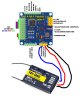
@miky94 top right of the pic it says uart1.
On them pins. 5v-G-signal rx.

I own a turnigy evo & it's a good tx.
Ia6c rx on uart1.
I never used a wii but its got to be better than a naze. Ibus is serial rx in receiver menu. Then in the evo menu turn on ibus.
Ports menu on Betaflight apply serial rx on uart1. You should be good to go.
 
Last edited:
With a bit of fishing & another £$10 you could get a flysky-turnigy i6.
& programmable tx.
But out of them 2 posted it would be the turnigy.
 
Uart1 still,
sbus is ibus on that rx.
Just try it.
If not just turn off serial rx in ports and then change to rx ppm in receiver menu in the config tab.
Change tx menu back to ppm.
Tx should now work on ppm on uart1.
 
Sorry I got mixed up I thought you had a turnigy evo.
The cheap hobbyking & turnigy 6ch
Have no menu's so I'll check if they are pwm or ppm, they still go on uart1.
 
Sorry I got mixed up I thought you had a turnigy evo.
The cheap hobbyking & turnigy 6ch
Have no menu's so I'll check if they are pwm or ppm, they still go on uart1.
wait I'll explain, I bought a Turnigy Evolution W/TGY-IA6C receiver included, it supports ppm, s.bus and i.bus but I think my MultiWii FC only supports ppm and I don't know how to wire it
 
I see someone is using a T9X with that T6a rx so it's ppm aswell as pwm.
The transmitter is programmable with a pc

So just 3 wires needed
5v from rx channel 1 to 5v on uart1 pins
Ground on channel 1 to G on uart1 pins
Signal on channel 1 to rx on rx on uart1.

When wiring signal pins tx is out & rx is recieve. So obviously the T6a is sending out a signal & the rx receive pin on uart1 is the signal in. Some uarts have a tx pin, this is for sending signals back, basic setups don't use tx.
 
wait I'll explain, I bought a Turnigy Evolution W/TGY-IA6C receiver included, it supports ppm, s.bus and i.bus but I think my MultiWii FC only supports ppm and I don't know how to wire it
Still on uart1 then, but in betaflight still try serial rx in ports tab then apply ibus in the rx menu in the config tab.
Try both configurations on each ppm & sbus pin on the ia6c pins. It will definitely work on ppm but sbus/ibus is a faster signal giving better response.
 
On this diagram it says serial rx so if yours is same it may work with ibus.
Worth a shot.
Im just not sure as never used a MWii
 
to remove any doubt:
using ppm this way should work
even better would be using ibus, connecting the FC uart rx to sbus pin instead of ppm, if the FC supports it
on the transmitter is there anything else to do besides setting the output mode and bind it to the receiver?
about the FC upgrading, I see many different F4 omnibus boards, is there anyone to avoid? what should I pay attention to?
 

Attachments

  • Senza-titolo-2.jpg
    Senza-titolo-2.jpg
    185 KB · Views: 4
  • F4-PRO-V2-Controllore-di-Volo-Built-In-OSD-BEC-Drone-per-Betaflight-A-Basso-Rumore.jpg
    F4-PRO-V2-Controllore-di-Volo-Built-In-OSD-BEC-Drone-per-Betaflight-A-Basso-Rumore.jpg
    584.9 KB · Views: 5
All omnibus boards are OK IMO
Better than naze by far I can't speak for MW but it is one of the oldest if not the oldest.

Yes try the ppm pin on ia6c as both serialrx and ppm in RX menu on config tab.

Try the sbus pin on ia6c as serialrx in RX menu in config tab. Set uart1 to serial RX in ports tab.

So you have 3 options & one of them will definitely work.
That being ppm pin on ia6c & set to rx-ppm in receiver menu in config tab.
 
If you can get one try the Omnibus F4SD AIO IMG_20190115_181713407-1024x575.jpg easy to wire with a good layout.
The ESC ground signal wires just go on the esc's main power ground pad.
I could get this stack lower but there is riim for a vtx below or ontop . this is my LOS quad. IMG_20190115_182417663-768x1367.jpgI always keep my top plate online with the props for better CG.
1300 lipos tend to weigh about the same as a build.
 
Even this old SPRF3 is over 3years old with over 100 bad crashes and I took all the jst sockets off and just direct solder to it. This is the cheapest board i would buy now for builds I do for ppl.
Its coated in liquid silicone and the build was dropped in the bath full of water.
It worked and still does.IMG_20190115_183721443-768x1367.jpg
 
to remove any doubt:
using ppm this way should work
even better would be using ibus, connecting the FC uart rx to sbus pin instead of ppm, if the FC supports it
on the transmitter is there anything else to do besides setting the output mode and bind it to the receiver?
about the FC upgrading, I see many different F4 omnibus boards, is there anyone to avoid? what should I pay attention to?
I wired the receiver as in the image, and I binded it to the transmitter, but I can't arm the motors.
before I used to arm them by sending yaw 2000 and throttle 1000 using MSP protocol via FTDI, but now using the transmitter it doesn't work.
I tried open the MultiWiiConf software but when I connect the receiver I no longer receive information from the FC, ideas?
 
Modes menu in beta flight

Put arm switch on auxiliary 1
Angle mode on auxiliary 2
Horizon mode on auxiliary 2

Now with the tx not having its own menu screen you will have to plug the tx into a pc & apply the Aux1 to any 2 position switch you like.
But Aux 2 has to be the 3 position switch.
Most are SWC.
The first position will be angle mode
Second will be horizon
And the 3rd is acro mode by default.

It's dangerous having it the stock way as this can be replicated in flight causing a disarm mid-flight.
 
After doing this you should notice toggling the switches on the tx move the ranges in receiver & modes tabs.
You need to make sure that angle & horizon fall within the values for the range of the switch.
Angle should be ok but you may have to move the horizon slider to the middle so it lines up.
 
Can you not get into the GUI at all.
Did you try changing to a different com port. Sometimes they jump around adding different things.
Run through them all.
 
Back
Top