Scratch Build - T-Motor F7 Stack - F7 FC, F45A V2 3-6S 4-in-1 ESC Combo

C.B. Russell

Active Member
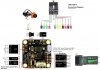
Got the T-Motor F7 Stack but no manual other than a picture. Does anyone know where build video or manual may be found?
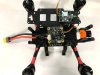
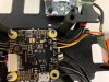
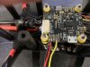
My build.
T-Motor F7 Stack - F7 FC, F45A V2 3-6S 4-in-1 ESC Combo
TBS Unify EVO 5.8GHz Video Transmitter
XILO Stealth 2206 2600KV Motors
RunCam Split 3 Micro 19x19mm FPV / HD Camera
TBS Triumph Pro Antenna
Custom 3D Frame
Info-thoughts?
Thanks
 
Sorry what is it your looking for exactly? The details page has the pin breakouts i think any betaflight setup vid would be enough plus the wiring diagram, to get most of it hooked up. Which part are you stuck on or particular component do you struggle with connecting?
Checked on both and no-joy?
 
Hey guys, me again, the highly confused person. I have watched many, many videos, read the pinouts and I’m impressed with this flight controller, so many different ways to connect things but… specifically I would like to connect the camera (RunCam Split 3 Mini), transmitter (TBS Unify EVO) and receiver (FS-iA6B) to the T-Motor F7 FC in such a way as to not fry this slightly expensive wonder. I don’t have a problem with soldering big or small. Although this is my first build, I have gotten to a custom 3D printed carbon fiber frame with motors the 4 in 1 esc wired and soldered. I have included a diagram for connections and pic of work in progress. I would greatly appreciate anyone who would add to the diagram as to the best way to connect wires, please.
 

Attachments

  • Connections.jpg
    Connections.jpg
    78.4 KB · Views: 9
  • IMG_0385.jpg
    IMG_0385.jpg
    68.7 KB · Views: 9
  • IMG_0387.jpg
    IMG_0387.jpg
    116.6 KB · Views: 7
Sorry what is it your looking for exactly? The details page has the pin breakouts i think any betaflight setup vid would be enough plus the wiring diagram, to get most of it hooked up. Which part are you stuck on or particular component do you struggle with connecting?
Please check out my post. Any info is appreciated.
 
Last edited:
Please check out my post. Any info is appreciated.
Looking pretty good so far. You might want to get or use some side cutters to snip that little extra bit of GND wire from the cam board going to FC but doesn't appear to be bridging any connection so should be fine as is.

For receiver hook up just need power to receiver so red wire to 5v and black to gnd (any 5V or gnd pad on the FC will typically work basically all gnd is connected to all other gnd, generally speaking). Can continuity check the pads before adding wires to verify for yourself. Then just need signal going into correct RX pin if you get it wrong nothing breaks it just won't see the signal until you correct the port in settings or physically reconnect the wire.

Regarding frying things you don't need to worry about it too much until you go to connect battery but also so long as there is no reversed polarity (gnd and 5V swapped) and no short between power and gnd (use continuity checker to check) then you should be good. Having a lab bench power supply or any sort of adjustable or current limited supply for power adds reassurance but isn't necessary.
 
Most computer USB chipsets will only put out 500mA of power at max and most of the circuits can deal with that current for quite a while before the heat becomes a problem. Conversely once you hook up battery there is a ton of amperage available and current will flow based on resistance of components and voltage. Ohms law in action with current only limited by internal resistance of battery plus components, so probably 100 or 1000A territory for a short time until something cooks.
 
So yah things to verify you didn't do:
Short power and gnd anywhere.
Put power into a signal line (short between power and signal pads)
Reverse polarity swapped a red and black somewhere where red is positive and black is gnd or negative.
 
Looking pretty good so far. You might want to get or use some side cutters to snip that little extra bit of GND wire from the cam board going to FC but doesn't appear to be bridging any connection so should be fine as is.

For receiver hook up just need power to receiver so red wire to 5v and black to gnd (any 5V or gnd pad on the FC will typically work basically all gnd is connected to all other gnd, generally speaking). Can continuity check the pads before adding wires to verify for yourself. Then just need signal going into correct RX pin if you get it wrong nothing breaks it just won't see the signal until you correct the port in settings or physically reconnect the wire.

Regarding frying things you don't need to worry about it too much until you go to connect battery but also so long as there is no reversed polarity (gnd and 5V swapped) and no short between power and gnd (use continuity checker to check) then you should be good. Having a lab bench power supply or any sort of adjustable or current limited supply for power adds reassurance but isn't necessary.
Uart 1-3 or 5?Correct? This is the receiver connection. I see what ur talkin about on that ground wire.Fixed!
 

Attachments

  • IMG_0389.jpg
    IMG_0389.jpg
    66.5 KB · Views: 1
Last edited:
Uart 1-3 or 5?Correct? This is the receiver connection. I see what ur talkin about on that ground wire.Fixed!
K, now on to the tbs unify evo 5.8ghz video transmitter install. Connection to VTX area?
 
Yup I think RX1 is typically used for receiver input. You'll have to check manual for FC if want to be sure since some of them only have ability to handle certain protocols with certains pins of the MCU (brain/big black chip in middle of board).

According to the diagram this one will support sbus protocol from the receiver on any of the UARTs but they also show using R3 so that might be the default they ship firmware set to use but you can change this in the ports tab in betaflight configurator. Before hooking everything up (or in the middle) can plug in the FC to computer just make sure no power pins are getting shorted and can connect to the board with betaflight configurator just to poke around a bit in there. Worth watching a vid or two on betaflight configurator itself Joshua Bardwell has a ton amongst others.
Yep, that's what I was saying earlier!Different ways to connect. He is the one I've watched most. But... any info on the TBS Unify EVO connections with the wires that came with it?
 
In general for vtx just need three wires the power and gnd are two and the third is video signal into the vtx which needs to come from the video out or Vo pin on the FC board. Usually the vtx will have pretty wide power input options regarding voltage so you may want to give it direct battery power and put a big capacitor on the main power input lead near the vtx so if power from ESCs is a bit noisy or makes the voltage dip a bit the capacitor near the vtx will help keep it's power more consistent.

If trying to control the vtx from the FC or otherwise there may be other wires to connect but usually I just set it with button on the vtx and typically buy ones that show the channel and power output clearly on a little LCD character display.
Good morning.

K , the TBS Unify EVO takes 7-26 volts, VTX jumper bridged to battery, yellow wire connected to Video out and +/- (Red /Black) respectively. I understand this but…three other wires go to camera directly (Not used as cam it connected via cam section) and two wires (Red And Green) that can be used for smart audio, do I need these connected with this set up?
 
Yup should be good with just the three connections in terms of some video getting sent out. The smart audio is an optional way to use on screen menus from your goggles or display to change the vtx power output or channel settings. If the vtx has no display on it then I'd definitely hook up the smart audio lines too. There is one tricky thing with uart in that tx out of one thing goes to rx on the other and vice versa, so hook up smart audio tx from VTX to one of the RX pins on FC and go from RX pin on VTX to the corresponding TX pin on FC.

I believe the other set of serial pins etc. You might see on there are for Daisy chaining the transmitters but never done that myself.
 
Last edited:
Back
Top