GlassKnees
Well-Known Member
Well, after spending a considerable amount of time modifying and tinkering with an Elev-8 quadcopter, I finally decided I have to switch to another airframe. If you followed some of my exploits then you know that I tried different motors, added a gimbal, etc. but was sorely disappointed in my short endurance times. Adding larger batteries added weight to the aircraft, straining the motors, so I found some great new motors - T-Motor MN3520's that I found at a bargain price of $46! But they require a 6S lipo. More powerful motors mean larger batteries, which meant more weight....
In addition, the 16000 mAh lipo I bought is so big that I needed to replace the landing skids, so I mounted landing gear that I salvaged from a crashed Tarot 680 Pro hexcopter. The problem with this is that they had to be mounted to the bottom chassis plate which is plastic and bent under the strain:

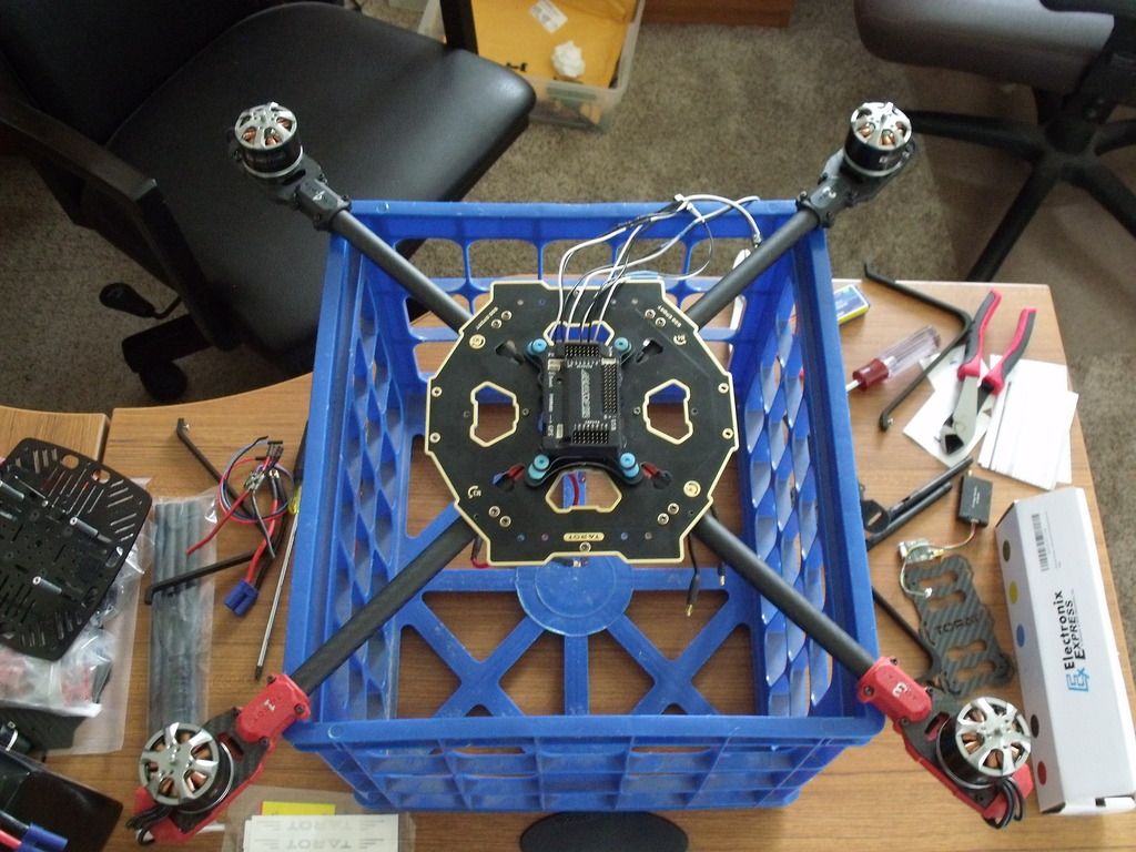
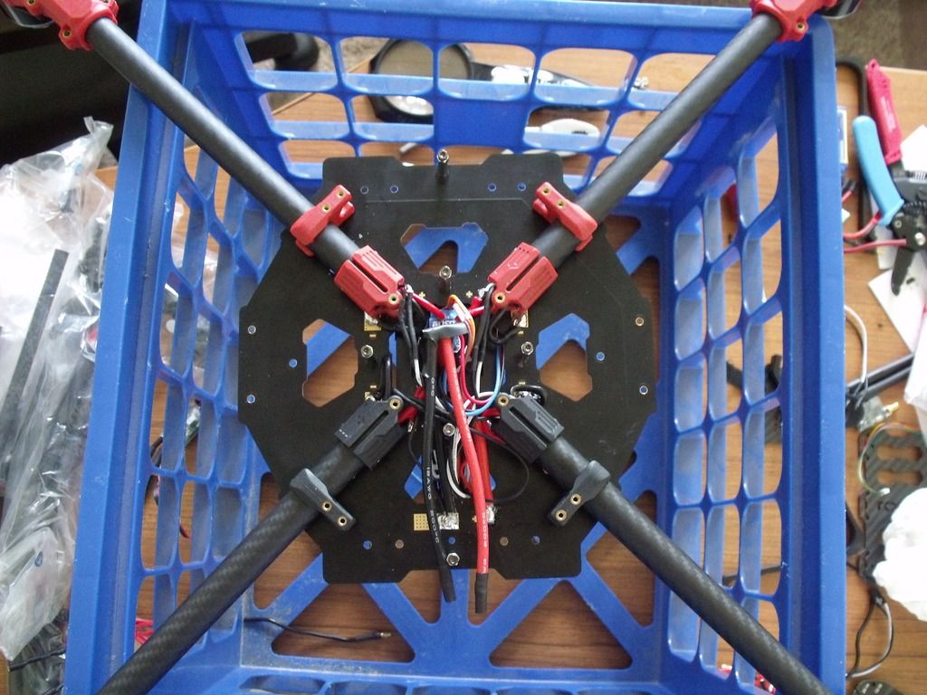
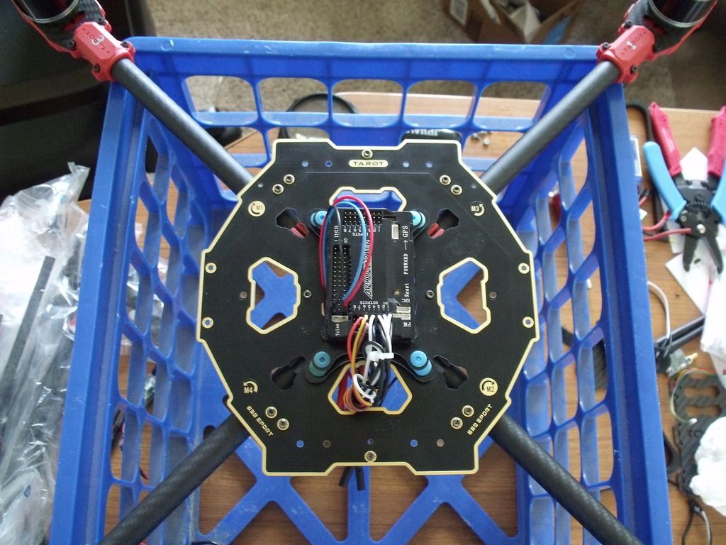
So, this is is my motivation for a new build. The Tarot 650 Sport is a much stronger airframe and the chassis plates are much stronger - I've seen videos where builders have installed 6S lipos with no problem. I'm hoping to end up with a better aircraft that will provide me with longer flight endurance for video shoots.
The kit arrived today:

And I began the unboxing:

Here is the elev-8 that has the components that I will use:

Components include:
T-Motor MN3520's
30 A OPTO ESC's
AMP 2.6 Flight Controller
Ublox 7M GPS/compass
AttoPilot Voltage/Current Sense breakout module
Feiyu-Tech Mini 3 Axis Gimbal
F801 8 Channel Receiver
I plan to document the build, so stay tuned!
In addition, the 16000 mAh lipo I bought is so big that I needed to replace the landing skids, so I mounted landing gear that I salvaged from a crashed Tarot 680 Pro hexcopter. The problem with this is that they had to be mounted to the bottom chassis plate which is plastic and bent under the strain:
So, this is is my motivation for a new build. The Tarot 650 Sport is a much stronger airframe and the chassis plates are much stronger - I've seen videos where builders have installed 6S lipos with no problem. I'm hoping to end up with a better aircraft that will provide me with longer flight endurance for video shoots.
The kit arrived today:
And I began the unboxing:
Here is the elev-8 that has the components that I will use:
Components include:
T-Motor MN3520's
30 A OPTO ESC's
AMP 2.6 Flight Controller
Ublox 7M GPS/compass
AttoPilot Voltage/Current Sense breakout module
Feiyu-Tech Mini 3 Axis Gimbal
F801 8 Channel Receiver
I plan to document the build, so stay tuned!