GlassKnees
Well-Known Member
I have built two Tarot multicopters, a 680 Pro Hexcopter and a 650 Sport quad. In addition, I am currently building a 650 Iron Man. Based on my experiences, I have the following critiques with Tarot designs.
The first, and possibly the most significant flaw is the design of the motor mounts - they encourage placing the ESC underneath the motor (for confirmation, watch YouTube videos of Tarot builds).
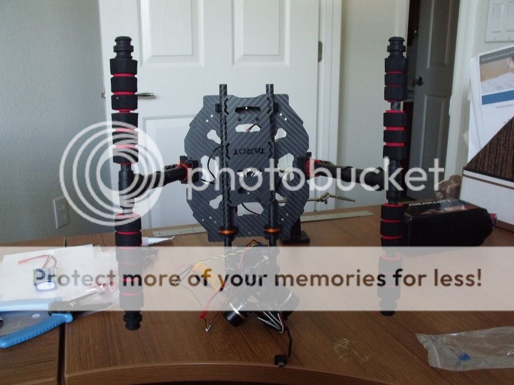
Here is a picture of a modified Parallax Elev-8 quad where I used the Tarot motor mounts and you can see the ESC mounted below the motor:

The problem with placing the ESCs next to the motors is that you have to lengthen the power and ground leads that go to the ESC from the power distribution setup, which is a pcb built into one of the chassis plates (except for the Iron Man - you have to come up with your own power distribution setup).
Lengthening the wires from the power source to the ESC will cause high voltage spikes due to the switching action of the ESC - imagine running a water faucet at full blast and then suddenly shutting it off; you will hear a loud thunk as the water pressure momentarily builds because the water suddenly has no place to go. You have the same situation except you get momentary voltage spikes. Eventually, the ESC gets damaged with potentially catastrophic results.
The solution is to wire a low ESR electrolytic capacitor across the power and ground leads - you will need about 220 microfarads for every 4" of wire length. Nobody warned me about this when I built my copters, and I have had two mysteriously fall out of the sky even though they had both previously flown well. If you don't want to bear the expense and hassle of adding caps, then your only other solution is to install the ESCs closer to the power source and lengthen the three leads going to the motor. I've read that the inductance in the motor's windings will minimize any noise issues.
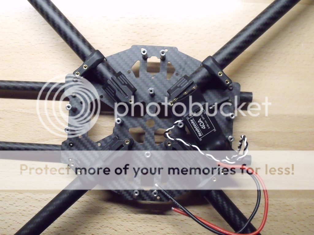
This leads to my next critique - the chassis plates are too small to accommodate installing the ESC's within the aircraft body. Here is a pic of the chassis for the 650 Iron Man:

Clearly there is no room for the ESCs. In addition, I have to install some sort of power distribution mechanism - I chose a harness (salvaged from one of the crashes) instead of a separate pcb board. Also, I needed to install a BEC to power the receiver as I'm using OPTO ESCs.
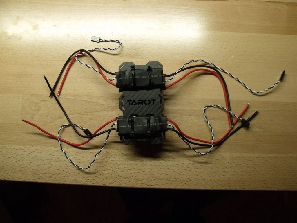
My approach was to fashion an ESC "module" using standoffs and two Tarot battery plates:

This created another problem - This module hangs underneath the body, where my 13000 mAH 6S lipo will be slung - I have to fashion a styrofoam cover that will fit over the ESCs and provide a flat surface for the lipo. But I fret about adequate airflow for the ESCs.
The design of the 650 Sport and Iron Man models allow for folding the booms in order to facilitate transport. After all, they are large aircraft! But after installing all the wiring, I don't believe that I will be able to fold the booms. Here, I've completed all the power system wiring:

You are looking at the bottom chassis plate with the booms mounted in their respective clips. The rear of the aircraft is in the foreground. The arms are supposed to pivot to the left and right sides, but as you can see, there's a lot of wiring congestion. I won't know for sure until I mount the top plate if I will be able to fold the arms - this would be useful, especially given that I will be using 17"propellers (they are foldable)!
Next up are the landing skids - they are carbon fiber tubes fitted through a T joint:

The problem is the tubes endure stresses at the edge of the T-joint during landing, eventually causing them to fail structurally. I solved this problem by ordering nylon rods having the same diameter - they are heavier than the carbon tubes but are more resilient, flexing during a hard landing.
Finally, this is a nit, but there are no accommodations that I could find, for mounting different flight controllers on top. I'm an APM bigot and I have to drill holes in my APM mount in order to use the existing holes on the chassis plate.
If I ever build another large quad, I will look at designing and fabricating my own frame.
The first, and possibly the most significant flaw is the design of the motor mounts - they encourage placing the ESC underneath the motor (for confirmation, watch YouTube videos of Tarot builds).
Here is a picture of a modified Parallax Elev-8 quad where I used the Tarot motor mounts and you can see the ESC mounted below the motor:

The problem with placing the ESCs next to the motors is that you have to lengthen the power and ground leads that go to the ESC from the power distribution setup, which is a pcb built into one of the chassis plates (except for the Iron Man - you have to come up with your own power distribution setup).
Lengthening the wires from the power source to the ESC will cause high voltage spikes due to the switching action of the ESC - imagine running a water faucet at full blast and then suddenly shutting it off; you will hear a loud thunk as the water pressure momentarily builds because the water suddenly has no place to go. You have the same situation except you get momentary voltage spikes. Eventually, the ESC gets damaged with potentially catastrophic results.
The solution is to wire a low ESR electrolytic capacitor across the power and ground leads - you will need about 220 microfarads for every 4" of wire length. Nobody warned me about this when I built my copters, and I have had two mysteriously fall out of the sky even though they had both previously flown well. If you don't want to bear the expense and hassle of adding caps, then your only other solution is to install the ESCs closer to the power source and lengthen the three leads going to the motor. I've read that the inductance in the motor's windings will minimize any noise issues.
This leads to my next critique - the chassis plates are too small to accommodate installing the ESC's within the aircraft body. Here is a pic of the chassis for the 650 Iron Man:

Clearly there is no room for the ESCs. In addition, I have to install some sort of power distribution mechanism - I chose a harness (salvaged from one of the crashes) instead of a separate pcb board. Also, I needed to install a BEC to power the receiver as I'm using OPTO ESCs.
My approach was to fashion an ESC "module" using standoffs and two Tarot battery plates:

This created another problem - This module hangs underneath the body, where my 13000 mAH 6S lipo will be slung - I have to fashion a styrofoam cover that will fit over the ESCs and provide a flat surface for the lipo. But I fret about adequate airflow for the ESCs.
The design of the 650 Sport and Iron Man models allow for folding the booms in order to facilitate transport. After all, they are large aircraft! But after installing all the wiring, I don't believe that I will be able to fold the booms. Here, I've completed all the power system wiring:

You are looking at the bottom chassis plate with the booms mounted in their respective clips. The rear of the aircraft is in the foreground. The arms are supposed to pivot to the left and right sides, but as you can see, there's a lot of wiring congestion. I won't know for sure until I mount the top plate if I will be able to fold the arms - this would be useful, especially given that I will be using 17"propellers (they are foldable)!
Next up are the landing skids - they are carbon fiber tubes fitted through a T joint:

The problem is the tubes endure stresses at the edge of the T-joint during landing, eventually causing them to fail structurally. I solved this problem by ordering nylon rods having the same diameter - they are heavier than the carbon tubes but are more resilient, flexing during a hard landing.
Finally, this is a nit, but there are no accommodations that I could find, for mounting different flight controllers on top. I'm an APM bigot and I have to drill holes in my APM mount in order to use the existing holes on the chassis plate.
If I ever build another large quad, I will look at designing and fabricating my own frame.
Last edited:

