Hi, everyone!
Just joined the forum to look for hint to repair a Redpawz R020 drone.
I've recently found this drone in the woods. I've brought it home. No battery charger, no controller, no rotor shields.
Before spending any amount of money in spare parts (at least a battery charger), I would like to know if it is worth to try to revive the thing.
I made several test yesterday:
- recharged the batteries with a lab power supply => the drone turned on
- connected via WiFi to the drone with my phone, and tested the camera using the HTS UFO app => can connect to the drone and see the images => the main processor works
- tried to control the drone with the app (I haven't yet understood if I actually can control this drone with the app...) => no motor movement
- tried to power the motors directly to see if they spin => all 4 motors spin when manually powered
So, why is it not working?
2 main hypotheses:
1) I actually can't control the drone via app
2) there's some problems in the "signal route" between the main processor and the motors
Regarding point (1), the question is quite easy: does anyone know if I can control this specific drone model via WiFi?
Point (2) is more complicated. But the short answer is: shure there are some problems!
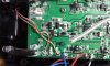
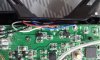
I've disassembled the drone and noticed that there are 4 SMD components just before the motors output wires, and 3 of them are noticeably fused (see attached image). No wonder they won't spin... Fourth one looks ok, but maybe it is just less damaged.
The problem is that I can't understand what these components are. They are 3 pins SMD. From the not blown one I can read something like "XORR" or "XORB", with what looks like a "22" written vertically. Couldn't find any info on the web.
I really don't know anything about drone (and motors in general) electronics, but maybe you can tell me which components are typically put before the motors. I suppose it could be a transistor that feeds the current form the battery when the processor sends out a PWM (processors pins have typically low current outputs and can't power a motor). Sounds reasonable? What could I use to replace these ones?
My next test will be to measure (with an oscilloscope) what the processor sends to these components, to see if the signals changes (or at least something arrives) when playing with the app.
Many thanks for all the hints you'll give me!
-- EDIT --
Weel, while writing this thread, and realizing these components could be transistor, I've found this:
 www.transistormosfet.com
Sounds good...
www.transistormosfet.com
Sounds good...
Doubt I will find any datasheet for these, anyway. If someone have hints on the specs for alternatives I'll be thankful!
Just joined the forum to look for hint to repair a Redpawz R020 drone.
I've recently found this drone in the woods. I've brought it home. No battery charger, no controller, no rotor shields.
Before spending any amount of money in spare parts (at least a battery charger), I would like to know if it is worth to try to revive the thing.
I made several test yesterday:
- recharged the batteries with a lab power supply => the drone turned on
- connected via WiFi to the drone with my phone, and tested the camera using the HTS UFO app => can connect to the drone and see the images => the main processor works
- tried to control the drone with the app (I haven't yet understood if I actually can control this drone with the app...) => no motor movement
- tried to power the motors directly to see if they spin => all 4 motors spin when manually powered
So, why is it not working?
2 main hypotheses:
1) I actually can't control the drone via app
2) there's some problems in the "signal route" between the main processor and the motors
Regarding point (1), the question is quite easy: does anyone know if I can control this specific drone model via WiFi?
Point (2) is more complicated. But the short answer is: shure there are some problems!
I've disassembled the drone and noticed that there are 4 SMD components just before the motors output wires, and 3 of them are noticeably fused (see attached image). No wonder they won't spin... Fourth one looks ok, but maybe it is just less damaged.
The problem is that I can't understand what these components are. They are 3 pins SMD. From the not blown one I can read something like "XORR" or "XORB", with what looks like a "22" written vertically. Couldn't find any info on the web.
I really don't know anything about drone (and motors in general) electronics, but maybe you can tell me which components are typically put before the motors. I suppose it could be a transistor that feeds the current form the battery when the processor sends out a PWM (processors pins have typically low current outputs and can't power a motor). Sounds reasonable? What could I use to replace these ones?
My next test will be to measure (with an oscilloscope) what the processor sends to these components, to see if the signals changes (or at least something arrives) when playing with the app.
Many thanks for all the hints you'll give me!
-- EDIT --
Weel, while writing this thread, and realizing these components could be transistor, I've found this:
XORB price list, XORB photo |transistor mosfet
XORB price list from transistormosfet.com offers you the best XORB photo,transistor and XORB mosfet.
Doubt I will find any datasheet for these, anyway. If someone have hints on the specs for alternatives I'll be thankful!
Attachments
Last edited: