First Quad: Power Distribution Issues

Owen Hardy

New Member
Hello All,

I recently decided that I wanted to build a quad, so I did some research on which parts were best. I came up with the following parts for the 'basics':

Motors: NTM Prop Drive Series 28-26A 1200kV
ESC: Turnigy Plush 18A
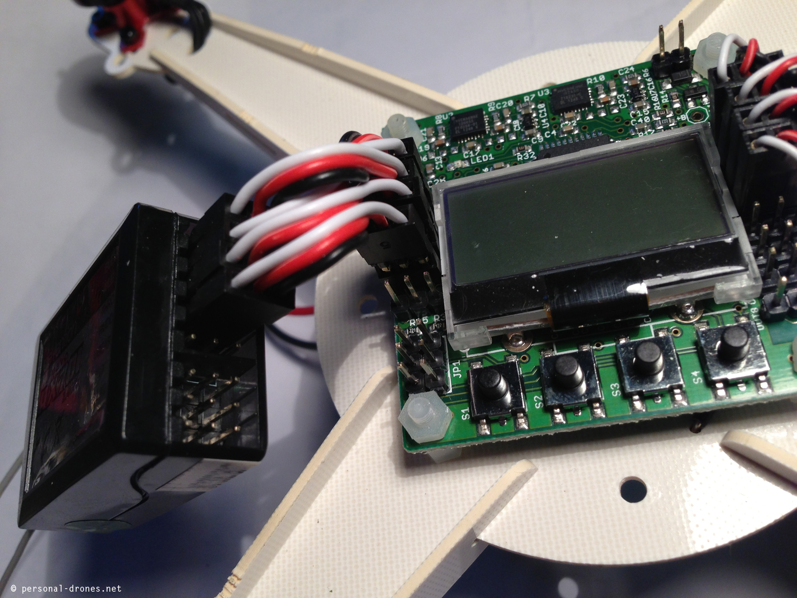
Control Board: KK 2.1.5 Multirotor Control Board
Power Distribution Board: HobbyKing Quadcopter Power Distribution Board
Battery: Turnigy 2200mAh 3S 40C Li-Po Battery

Once I had finished assembling the frame and installing the motors with the ESC's, I ran into an issue with powering the KK board. I initially used the black 2-pin connector on the HK Power Distribution Board and plugged it into the Voltage Sensor header on the KK board. I soon realized that this was wrong, but I tried to supply it 5V via the M1 input from my M1 ESC, but that too failed. I continued to look around the internet looking for answers, but nothing turned up. What I thought was odd was that all of the ESC's gave the initial arming sequence and some beeps, but the KK board still was not powering on. I was wondering if someone could please give me some guidance on what I am doing incorrect, as I really would love to have my very own quadcopter!

Thank you in advance for your time,

Owen
 
Last edited:
The board should be getting power from one of your ESC's since those have BEC's. Based on the manual, one of the ESC's should be good since they have 5V BEC's:

The Flight Controller Board must always have a source of +5v from an ESC, either one of the
motors ESC or from a separate unit feeding the Receiver. If each ESC has a BEC (normal unless
OPTO types) then it may be necessary to remove the power feed from the other ESC, usually by
cutting the power line (RED) Cable on the other ESC.

They definitely aren't OPTO, so you don't need an additional power source. The only thing I can think of is that you have the connections flipped around (on the wrong pins) - although the red is in the middle, so I think you'd still get power. It could also be a bad board. Have you contacted Hobby King about it? Honestly - it's pretty straight forward to at least get to the point where you have power to your board.
 
I hope you didn't roast it when you plugged it into the power distribution board (straight off the battery)! If it's looking for 5v, hitting it with 11 may be bad. You may want to try to rig a USB power adapter to feed it power, just to see if it yet lives.

I bought a power module along with my controller (ArduFlyer APM). I've read that the power off of ESCs can be a bit noisy for the controller. I'd get a 5v UBEC and tack it to your power distribution board -- probably the same one I got (from HobbyKing). I modded my power module, removing the honking leads on both ends and just using smaller wire soldered directly to the distribution board, since it wasn't acting as a pass-thru for the battery.
I've ordered another to power my camera, but I'll probably run my FPV transmitter directly off the distribution board. When I ran it off the 4s battery it seemed to work fine.
 
Last edited:
The board is working because when I plug it in via USB it turns on. Another thing I should mention is that the ESC's seem to be giving the error code of the incorrect (low) battery voltage. I have purchased two power distribution boards because I shorted the first one out twice, but fixed my mistake after shorting it out again with a new power distribution board.
 
Last edited:
Have you tried a different battery? Or have you tried plugging a different ESC into the board? Also - I was kind of wrong above when I said red in the middle means it doesn't matter. That just means you won't cause a short, but you still need black on the correct side to complete the circuit. Have you tried flipping the ESC to control board connections around to use the opposite pins?
 
I've heard the ground is always the out-board pin; the signal always the inboard pin. If they're rotated 90 deg., that means the signal is on top and the ground on bottom. On ESC leads, the signal is generally the lightest color with the darkest being at the other end of the connector -- ground.
My ESCs are brown, red, orange -- the brown is ground, the orange signal.
 
Have you tried a different battery? Or have you tried plugging a different ESC into the board? Also - I was kind of wrong above when I said red in the middle means it doesn't matter. That just means you won't cause a short, but you still need black on the correct side to complete the circuit. Have you tried flipping the ESC to control board connections around to use the opposite pins?

Yes, I have tried to switch the servo wire-->KK board, but that does not work. So are you recommending that I order a 5V BEC then?
 
The ESC's have a 5V BEC built into them, so that should not be necessary. Do you have a picture of how everything is connected to the control board?
 
If I'm not mistaken, the white wire from the ESC is the data/signal, so it needs to be attached to all four ESC's. Also, I believe you have them turned around. The black wire should be on the outside as Hugh said. Every image I've seen has it that way.

Did you cut the white wires from the connectors, or pull them out cleanly?

 
Looking at the third picture I'm not sure that power distribution board has enough integrity left! It looks like the PLUS "trace" has seen some "action" and may not be feeding the left or bottom ESC leads on that pole. You may want to scab on at least one thick wire jumper across the apparent destruction. I think that board has another set of trace pads on the back, but it'd be good to try and restore its original current capacity if possible. If you're placing another HobbyKing order, just add another power distribution board to it, and make a note to replace it the first time you lunch your quad and have to do serious surgery.
And second what MM said on the ESC signal leads. Plugging them into the controller backwards can take the controller out, but it looks like you eliminated the signal and power leads on three of them too. If you cut them off, you can slice off the shrink wrap on the ESCs and replace the missing wires there, using servo wires. You'll be able to see where each color went -- the ESCs don't necessarily need to be replaced.
It's odd that those ESCs have two black power leads instead of a red and black. Were plus and minus clearly marked? I see you soldered on the 3.5mm mini-bananas. I opted to remove them and solder the ESC leads directly to the board. I expect your ESCs came with 4mm banana plugs on both ends?
 
After what Hugh said, I realized the wires are soldered directly into the banana plugs. Honestly - you can get a PDB without those and solder to the board, or better yet, you can solder male banana plugs to the wires (which is the easiest soldering you'll ever do), then plug them in to the PDB female plugs. This is good if you're beginning especially in case you put the wires in the wrong places and you need to move them.
 
Yeah, the black and red bands came off in the soldering. http://www.hobbyking.com/hobbyking/..._Power_Distribution_Board_USA_Warehouse_.html It's pretty tough to get enough of the solder out of the connectors to plug in the 3.5mm mini-bananas after you've soldered into them, so this may wait until you swap that board. Or did I visualize the plus trace carnage incorrectly? It looks to me as if the lower left quadrant is hanging in the breeze.
 
Back
Top