building Li-Ion battery pack

how can I check specs using IR value? the iMAX B6 Mini measures it but which value should I get?
If seller guarantees me the specs I'll try and if it is not I'll ask for refud
The values are all kind of relative since it depends on the environmental conditions (temperature mainly) around the cell how the chemistry will play out and how much resistance the battery will create against the current https://batteryuniversity.com/learn/article/rising_internal_resistance, long story short can compare against known good pouch battery used to power the quad and see what the difference is between the cells given your measuring device and environment and compare them, like you can see in the link above it should be somewhere around 60-100milli-ohm across the whole pack (about 12-20mOhm per cell is usually what I see on my quad batteries, lower the better). You'll really want to use this to make sure the cells with the closest internal resistance to each other end up in p-groups together to guarantee similar discharge rates from all the cells in the group.
 
Last edited:
AWG ratings are typically for wire in the wall and assuming continuous current flow, in general I just try to match the AWG the batteries I'm using have since the manufacturer will typically have high enough gauge wires and would be a bottleneck anyway so no real reason to go any bigger, basically same applies to the ESCs I try to use either the existing power wires or same gauge the mfg ships with. With the quads using BLDC you have duty cycle based on throttle input so if you are at low throttle then duty cycle is low and the ESCs are quickly opening/closing the gates to let current flow to the coils in the wire so the current flow is basically turning on and off the more throttle the more on time (more complicated because RPM is changing too but this is roughly what the ESC handles).

What this boils down to is the amperage/current flow from the battery is going to have some constant baseline current to keep the FC/VTX everything else going and then will have some variable current flow to the ESCs depending on how high the throttle is pushed. If you are only having that high current for a few seconds then the wire won't have time to heat up and will have time to cool down while the throttle is low but at some point if the current stays high for too long it can start to melt solder connections. There's a more definitive write up here too:
https://oscarliang.com/wire-awg-chart-quadcopter-rc/
 
Thank you,
doing a reasoning similar to that of the choice of the battery c-rating, I consider as continuous discharge current the 100% throttle amps draw (though I'll keep it for short time and the burst rating would be enough), with a little margin for other components,
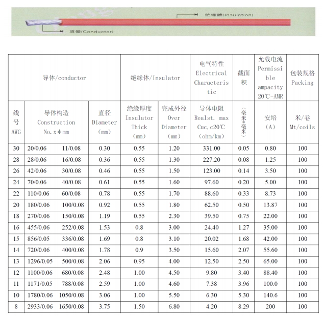
according to this table in your link a 16AWG wire (35A ampacity) should be right for me.
correct?
wire-awg-amp-diameter-resistance-chart.jpg

quadcopter's maximum draw is 30A and battery's maximum continuous discharge current is 40A.
XT60 comes with 12AWG wires with 88A ampacity which is more than the 60A permissible for XT60 itself.
 
Thank you,
doing a reasoning similar to that of the choice of the battery c-rating, I consider as continuous discharge current the 100% throttle amps draw (though I'll keep it for short time and the burst rating would be enough), with a little margin for other components,
according to this table in your link a 16AWG wire (35A ampacity) should be right for me.
correct?
wire-awg-amp-diameter-resistance-chart.jpg

quadcopter's maximum draw is 30A and battery's maximum continuous discharge current is 40A
XT60 comes with 12AWG wires with 88A ampacity which is more than the 60A permissible for XT60 itself.


Sure I mean the larger wire is going to have less resistance and always better to have more overhead weight permitting, but I use 12AWG on my esk8 setup and have never had issues with anything heating up really, can see the some data from it here (if you hover mouse over graph can see motor current vs regular (battery) current https://metr.at/r/6EGoI

If you measure the resistance of the length of wire you're going to use and know the max amperage your targetting you can simply do amperage squared times resistance to get power loss in the wire, that power loss is heat and needs to be move through the mass of the wire and out it's surface, if the heat can't escape quickly enough then it will build up and eventually melt the solder connections. Also good to keep in mind when looking at these charts there will be a difference in AC vs DC and PWM vs constant current flow, ultimately best way to know is to test things out and check to see if things are getting warm (infrared temp sensor can be helpful or instant thermometer to avoid the lick your finger and listen for sizzle method)
 
Of course this is in theory, if the ampacity in the table is the continuous ampacity, 16AWG should handle the quadcopter's maximum draw of 30A continuously without overheating, but being a selfbuilt battery I'll check it 10 times before taking off...
in the past I had problems with a Turnigy 4S LiPo, randomly the motors pushed 100% throttle without control, fortunately I had too small props and the quadcopter didn't disappear in the sky...
 
I think this is the best schema to use, is it right?
do I need to isolate for example the positive and negative terminals of the 2 bottom left cells I circled?
maybe on longest wires I should use lower AWG to lower the resistance.
why the cells voltage should be as close as possible if then I can balance charge them? is it harmful when I solder them together?
also to balance all the cells shouldn't there be a balance wire for each one?
 

Attachments

  • 6S2P0.jpg
    6S2P0.jpg
    141.1 KB · Views: 6
Really the easiest arrangement of cells is putting the parallel ones side by side since you can just bridge between them (positive to positive and negative to negative) with a nickel strip then but problem is always needing a spot welder and the cost of that vs pay off of being able to make custom arrangements of cells isn't typically worth it (this is why the NESE packs or similar despite being expensive and extra weight can still sell). As you said you'd need to basically isolate all the cells in the current arrangement also if you plan to direct solder the wires to the cells you're very likely to damage the cells so would definitely try some practice runs on less expensive or used/old cells before trying anything with the ones you plan to actually use. The main thing I've read on the esk8 forum is to have the soldering iron very hot so as to minimize the time you need the iron on the cell and minimize the heat transfer and roughing the surface of the cells then tinning them can help, but still would experiment with throw away cells first.

Regarding balancing the cells you need one balance lead to each pair of parallel cells, each set of cells in parallel will "self balance" between the two cells, if they are at a different voltage to start then as soon as you hook the positive to positive and negative to negative current will rush from the one with higher voltage to the one with lower voltage until they are at the same voltage (imagine two buckets, one filled half way and one fully filled if you hook a hose between the bottom of the two buckets the water rushes from the one with more to the one with less, the bigger the difference the higher the current/flow, in the analogy more water in bucket=more voltage). You want the cells you are going to hook in parallel to be very close in voltage for this reason you don't want a cell to take on 50A incoming current when it's designed to be charged at 1-2A. Hooking the parallel packs up in series the voltage difference isn't as much of a concern since you can use a balance charger to balance out the parallel pairs (can basically think of cells that are in parallel as just one bigger cell with double mAh of a single cell and double discharge rate).

---

Also think I mentioned it before too but packing all the cells into a smaller area is going to be ideal with regard to reducing the amount of angular momentum/inertia the craft has so ideally want the motors as far out as possible (as they are on the edge of the frame) and then want the rest of the weight as centralized as possible (basically reduce the leverage of the weight working against the motors when rolling/pitching).

https://cad.onshape.com/documents/c...990a4bde5cc0942058/e/f055e7cd9fcbafe12e8917c2
^^ that is basically the arrangement that's ideal in terms of packing the mass in one place as far as I can tell. You could hook pairs of cells next to each other as P groups and could flip some of those P groups to make the series connections all or at least mostly on one side.

Connections like this assuming the packing/arrangement above:

https://photos.app.goo.gl/DShqHN1Zjw1mkjXw8
 
Last edited:
the reason of this arrangement is that I want to put the cells inside the arms stacked on top of each other. and I think this is the way which allows me to use the shortest wires length. I'll buy a single cell charger to full charge every cell before solder so that they have all the same voltage. I bought cells with presoldered nickel terminal so that I won't solder directly on the pole of the cell, lowering the risk of damages.
 

Attachments

  • Senza-titolo-1.jpg
    Senza-titolo-1.jpg
    42.5 KB · Views: 1
  • Senza-titolo-2.jpg
    Senza-titolo-2.jpg
    20.4 KB · Views: 1
I'll post a simulation of the connections before starting solder.
the gain would be in dimensions, weight and safe. I wouldn't need a support and a case for the battery. my goal is a drone easy to disassemble and compact for portability.
 
I'll post a simulation of the connections before starting solder.
the gain would be in dimensions, weight and safe. I wouldn't need a support and a case for the battery. my goal is a drone easy to disassemble and compact for portability.
I feel like packing the batteries into the quad will make it more difficult to remove though or swap out... Typically when I go fly I have maybe 3 or 4 4S batteries and am swapping them out every 5 minutes or so if the cells are attached to the arms then will be difficult to remove vs a brick strapped in the center.
 
I'll use only that battery so I'll keep it always inside the arms that can be disassembled.
Can do whatever you want to do but imagine you'll want more than one battery of flight time unless you just need to maximize distance on a single battery or there's some other reason to do it. If you want something portable then something small like a mavic that folds and can be tossed in a backpack is more ideal (really my 5" quad easily fits in a backpack as well with props on). I'm just struggling to understand how this will be easier or better overall. Still always interested to see new designs so not trying to discourage but just want to make sure it's actually what you're aiming for with the build and not just wasted effort.
 
wanting to keep the budget low I prefer to build an efficient drone instead of buying more batteries, and having low throttle hover means also having power for a versatile quad.
I'd like to bring it on motorbike holidays to record videos.
still not sure about storage differences from LiPos.
 
Back
Top