Dronemadness
Member
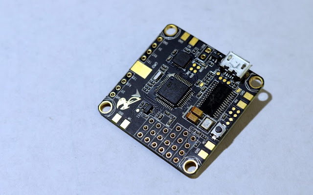
Betaflight F3 Flight Controller


For this review, I purchased the Betaflight F3. You can pick one up for yourself directly from Banggood HERE

Features
The Betaflight F3 flight controller touts an impressive resume. It is marketed as supporting every feature the Betaflight firmware has to offer – including all the new features of Betaflight 3.1. Here is a list of the notable features:
Built-in OSD with voltage and current sensing.
Built in PDB rated for 100A continuous, 160A burst.
Onboard 5V voltage regulator rated at 3A.
Full DSHOT support of all modes.
The best drone racing gyro on the market, hooked up to the processor via high speed SPI.
SD card slot for blackbox logging
Pad layout specifically designed for low-mess wiring, including edge-mounted pads for all ESC connections.
Boot button.
The Betaflight F3 Flight Controller has a pretty straightforward soldering alignment. All of the pins and pads are neatly labeled and located in logical places. Unlike most flight controllers or PDBs, though, soldering work must be done both on top and bottom of the board. I recommend you start with the bottom.

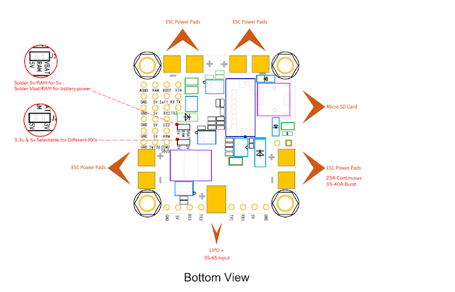
The main thing you’ll be soldering into this location is the power leads for all 4 of the ESCs. A pair of leads is located in each of the four corners of the flight controller. When soldering on ESCs, you have a couple of options. The best option is to desolder the power leads from the ESCs and solder them directly to the Flight Controller. The reason is that with the bottom of the flight controller installed in the frame, it is extremely difficult to solder wires from the ESCs directly onto the flight controller. This is what I tried in the build, and it was an excercise in frustration:
The ESC wires go under the board and are very difficult to solder once installed.
It is better to go the other way around. You want to install the flight controller on the frame with 4 sets of power leads pre-soldered and sticking out. From there you can then clip the wires to size and install the ESCs separately. This will make the installation much easier.
You will also want to bridge the appropriate pads for selecting the RAM voltage and the RX voltage:
RAM is the voltage that is sent to the video transmitter. You can select either the battery voltage (VBAT) or 5V to send to the VTX, but you must put in a solder bridge regardless. Failing to do this will leave your VTX unpowered. For my Chameleon build, I will be running VBAT to my VTX. I suspect most of you will be as well. The only VTX I know that uses 5V is the LaForge VTX.
The RX voltage jumper pads selects the voltage sent to the pin labeled “5V/3V” next to the “DSM2/SBUS” pin. If you are using an FrSky transmitter, you will want to bridge the 5V pad. For Spektrum guys like me, you will want to select 3V.
Finally, the battery positive lead is soldered to the rear side of the bottom board.

While there are many through-hole pins which can be accessed from both sides of the board, I recommend you do most of your work on the top of the board. This will make it easier to work on if you have problems since the board will be very difficult to flip over once installed.
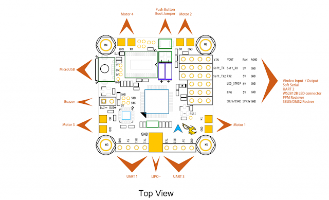
First up, you’ll want to install the ESC sigal wires. Like the power leads, each ESC has it’s own pads in each corner of the flight controller. Installing the signal wires to these pads should be very straightforward.
Next you’ll hook in the electronics. If you are going to use pin headers and servo connectors, solder them on now. Otherwise, go to work directly soldering your wires to the through holes. At a minimum, you’ll want to connect your serial RX, video transmitter and FPV camera.
The Serial RX should be hooked up to the labeled pads in the bottom of the pin headers on the right of the board.
The video transmitter will be hooked into VOUT/RAM/AGND. VOUT is the video feed, RAM is the voltage powering your video transmitter, and AGND is an isolated, noise-free ground source for your video feed.
The FPV camera is a bit more complicated. The Betaflight F3 FC doesn’t provide a power/GND source for the FPV camera so you should power it with the Vcc/GND output from your VTX. The video wire from your FPV camera should be hooked up to VIN on the flight controller.
From here, you’ll want to hook up any extra accesories you’ll be using. Pads and through holes for the buzzer, RSSI, and LED strips are provided.
And once again – solder the negative battery lead onto the top of the board.
Software Setup
Software set-up of the BetaFlight F3 is fairly typical of any Betaflight flight controller. Before you do anything though, you should find an SD card to use with Betaflight.
You’ll want to flash Betaflight 3.1 or newer to take advantages of all the awesome new features found in that version of the software. This board uses DFU to flash firmware, which can be a pain to use on Windows computers. The Betaflight documentation has a good guide on how to get this working.
Once you have the right version installed, you’ll want to do the same basic configuration you do on all Betaflight flight controllers.
You’ll also probably want to set-up your OS
GRAB YOURSELF A GOOD BOARD HERE ON BANGGOOD
