Newbie Drone build help needed

Hey everyone I have been following this thread and the info has helped me alot. I currently built (3D printed) a Spyda 500 Quadcopter by Gyrobot on thingiverse https://www.thingiverse.com/thing:241977 and now I need to add the hardware, flight controller, GPS, battery, radio trans/rec and the like. I have never built a Quad before so I'm really green at this and I appreciate all the help I can get. this Quad uses 10" props and that's about all I know, they say it is a very stable photography platform and that's what I'm looking for.
Thanks in advance for the help
ctdigger
 
Hi!

I’m currently planning for my first drone build, but I need some help to have any chance getting this right. I hope this is a good place to get that help. Below is a list of components I’ve put together from looking at what other have built out of similar components. The be able to move forward I initially need the following questions answered. I really appreciate any help I can get, and any additional tips or recommendations are very welcome.

Thanks in advance!

//Christian

1. Are the components I’m looking at compatible?

2. What Flight Controller should I chose?

a. LED Display on FC would be nice

b. Should I go for kind of all -in-one?

c. I’ve understood that some of the most popular options are Pixhawk, KISS, Betaflight (do they make both hardware and software?), FlightOne. Anything better to use out there? Easy setup/config is a good thing.

3. Is all I need to control the drone included in the chosen transmitter/receiver package?

4. Will 1700kv be the right size motor, do I choose a higher KV for a more powerful motor? Should I? More power is better, I guess.

5. I need help getting the right ESC for the motors I end up choosing.

6. Do I need to get some kind of antenna for the receiver?

7. What kind of battery and connector do I need for the setup?

Functions I want:

· Durable midsize and sable drone (rather bigger than smaller)

· Powerful enough to curry my GoPro or to later have Run Cam style FPV camera (not initially)

· Glonass GPS with RTH functionally for the drone

· Basic functions like altitude hold etc. But the more intel the better, without complicating things

iFlight XL8 V3 8-tums långdistans-freestyle ramsatsarm 5.5 mm för FPV Racing Drone

https://www.banggood.com/sv/IFlight...YCh32NQJVEAQYASABEgJQO_D_BwE&cur_warehouse=CN


EMAX RSII 2206 1600KV 1700KV 1900KV 2300KV 2700KV 3-6S Race Spec Brushless Motor RC Drone FPV Racing - 1700KV
https://www.banggood.com/EMAX-RSII-....html?rmmds=search&ID=519231&cur_warehouse=CN


Emax Simonk Series 12A 20A 25A 30A 40A ESC For Quadcopter QAV250 - 20A
https://www.banggood.com/Emax-Simon...kmClientCountry=SE&&ID=45170&cur_warehouse=CN


FlySky FS-i6 2.4G 6CH AFHDS RC Radio Transmitter With FS-iA6 Receiver for FPV RC Drone - Mode 2 (Left Hand Throttle)
https://www.banggood.com/FlySky-FS-...kmClientCountry=SE&&ID=42482&cur_warehouse=CN


ESC Connection Board Distribution Board For Multi-Axis Model
https://www.banggood.com/ESC-Connec...73.html?akmClientCountry=SE&&cur_warehouse=CN


Future 11*4.5 1145 Carbon Fiber Propeller CW for Fixed Wing RC Airplane
https://www.banggood.com/1145-Carbo...-p-1349563.html?rmmds=search&cur_warehouse=CN


AHTECH 3S 11.1V 2200mAh 85C 3S1P Graphene LiPo Battery XT60 Support 15C Boosting Charge For Racer
https://www.banggood.com/Infinity-3...-p-1060031.html?rmmds=search&cur_warehouse=CN


Flight controller

https://docs.px4.io/en/flight_controller/pixhawk4.html

Software

Betaflight? https://betaflight.com/
Christ1
this is what I 3D printed and trying to get equipment to get it into the air
https://www.thingiverse.com/thing:241977

Regards
ctdigger
 
Well, I think I have my equipment for my Spyda 500(thingiverse model) . ( build is similar to the F450, same size but upgraded). Gentlemen, please take a look and comment and suggest changes in my selections please.

Flysky i16 FS-i16 transmitter
BetaFPV supplier
BetaFPV 0802 12000KV Brushless motors
Matek ECHUB-6sPDB Flight Controller
iFlight Succex mini F4 FC stack 45A2-6s BLHeli s 4-1 ESC Speed Controller
Matek Sam-m8q GPS Module
Caddis Beetle VI 1800VTL Micro FPV camera + 5.8g VTL

I think that's it, if not please feel free to list what I missed
Thank You all for your help.
ctdigger
 
Motors are all over the place, those 12000kv ones spin very fast for really tiny props for micro size ones. To give you a rough idea:

300-800kv typically going to be somewhere around 4006 (40mm wide 06.0mm tall) maybe +/- some amount but not a huge difference. Typically going to be used with 10"-13" props made for relatively big sized rigs/frames like Tarot 680 build I've been working on. These are slow spinning for a given voltage, can run from 3S up to 10S maybe depending on the exact setup. Higher voltage (or more S) is typically more efficient for delivering high Watts regardless of the craft size but also more cells in series is a bigger/heavier battery at some level. Since they spin slower you are usually using a bigger propellor with these... since it's a bigger propellor it has more mass and therefore inertia and takes more force/torque to get it spinning hence the larger size of these motors compared to the faster spinning ones designed for smaller props/loads.

2000kv-3000kv range going to be somewhere around 2506 (25mm wide 06.0mm tall). Typically going to be used with 5" props and 3-4S batteries. More recently you might see people using around 1800kv motors and 6S instead of around 2600kv motors and 4S, it's basically reducing the RPM per volt and increasing the voltage so you end up at the same RPM but using higher voltage is again a bit more efficient (generally speaking).

10,000kv+ can vary in size and are sometimes brushed or brushless motors but are typically used for micros (2" or smaller propellors). Usually using a 1S or 2S battery with this size since the RPM for each volt is so high but they are also designed to be low torque so can't spin a big prop (need to be light weight so they can't be beefy and have all the extra copper and big magnets in the core to make them more torquey)

Other items you listed all look okay to me on the surface, I don't know if the 1800VTL is an exaggeration but if the VTX can only encode/transmit 700VTL (which I think is standard) then not sure those extra lines of resolution the camera sees will help (personally big fan of runcam options out there, with the "runcam split" series can get HD recording to an SD card and analog transmission with basically one module+cam/lens)

Would really double check everything on ecalc.ch though it's worth the license or at least pick out from the demo items stuff that is close to specs of things you plan to purchase to see what the lift to weight ratio, flight time, and other specs should be expected with the assembled thing.


-----

Edit also keep in mind info above is just pertinent to quadcopters and motors designed for them. There are lots of other BLDC motors out there that may be low KV and much different design like the Turnigy SK3 6374 149kv I used on a DIY electric skateboard, the can size 63mm wide and 74mm "tall" is substantially bigger than anything you'd see on a typical quadcopter but is ideal for the high torque and relatively low RPM needed for an electric skateboard (also lots out there designed for RC cars or boats where the requirements for torque/speed and weight requirements vary)
 
Last edited:
Also I think you should be aiming for something in the middle range there if it is ultimately a 5-6" propellor quad in the end, if it is needing to throw around a bigger prop then you end up needing to go more towards the first range of motors (low kv) if it is a tiny little guy that you can fly indoors and gets thrown around by the wind then it's in the last category (high kv)
 
This is what I got nothing mounted, just the 3D printed frame weight 12.80 Oz. my length from front arm to opposite arm is 21 inches, left front arm to left back arm is 14.5"

Remarks: Max current over limit of speed controller, bigger ESC needed
Defined model resulting in a all up weight less sum Dry weight.

Suggestions on "fixing" issues.
thanks for the help...again
ctdigger


ecalc: LOAD -1.5
HOVER FLIGHT TIME 20
ELEC POWER 100
EST TEMP 70
THRUST WEIGHT 5
SPECIFIC THRUST 11
 
Cool yah didn't mean to come off all negative just specs on the motors are going to matter a lot here, other stuff like the specific number of blades or exact pitch of them and things can just sort of fudge around and get more or less flight time or various kinds of performance but you'll need the motor kv and torque to be in line with whatever kind of prop you want. Generally speaking just want as big a prop as you can get on there without running into things or overlapping each other, if they go into clean "laminar" air it's better than turbulent air where the force it well get pushing through it is varying all over the place, so don't want them overlapping, but otherwise bigger disc is more air getting pushed === more force per spin === better efficiency, really loosely speaking.


Other components you have listed here I don't see major issues with but my experience of the bazillion products out there is limited too so YMMV
 
Check out specs shown here:

1587000882853.png

If you can show some screenshots of the numbers you're trying with I can suggest adjustments to components that should effect things but it is a bit of guess and check to see how things are effected. Basically frame size is fixed you know that, prop size you go with as big as your frame will support basically (make sure to account for extra stuff in the center of the quad or any asymmetry to the design). The motors, batteries, and prop combo will determine how many amps the ESCs need to be able to deal with to drive things at full throttle basically, so like you see if you have too much draw you just get more powerful ESCs. If the "Load" meter is in the green it means the C rating (max discharge) on the batteries is plenty high and could go with lower C rating ones (typically going to be a bit lighter but will have more voltage sag/dip when under load or amps being drawn).
 
Hi again experts! I took me some time to get a connector cable for my Omnibus F4 V5 Flight Controller, but I now have it and trying to figure out how to connect the cables correctly to the Matek FCHUB 6S PDB. As far as I can figure it out I need to connect things as in my home made schema (attached). Is this how to proceeed? What's "NV"? Doesn't that one need to be connected? Also, I've read this guide but don't quite get which options I should use for bridging the J16 current selection thing and hat the difference is. Anything else? No other volt selection I need to sort? What about next after this? As always, I'm very thankful for any help with moving this forward. Anyone? :-)
 

Attachments

  • myschema.JPG
    myschema.JPG
    211.1 KB · Views: 2
Last edited:
Hi again experts! I took me some time to get a connector cable for my Omnibus F4 V5 Flight Controller, but I now have it and trying to figure out how to connect the cables correctly to the Matek FCHUB 6S PDB. As far as I can figure it out I need to connect things as in my home made schema (attached). Is this how to proceeed? What's "NV"? Doesn't that one need to be connected? Also, I've read this guide but don't quite get which options I should use for bridging the J16 current selection thing and hat the difference is. Anything else? No other volt selection I need to sort? What about next after this? As always, I'm very thankful for any help with moving this forward. Anyone? :)

Can someone please give me a few pointers on this? I need to know I do this right and not brake any boards. If I'd known there were bundles for this I would have gone that route. Next time... Thanks in advance!
 
Can someone please give me a few pointers on this? I need to know I do this right and not brake any boards. If I'd known there were bundles for this I would have gone that route. Next time... Thanks in advance!
Your diagram looks good to me. Think a good thing to do is use multimeter to verify all the things you think are GND are connected (0 Ohm or put meter in short circuit detect mode and listen for the beeps while poking around). Also after hooking up the battery lead but before wiring anything else you can put meter in DC voltage checking mode and keep black probe on and GND connection and probe around with the Red to make sure the voltage on the pads you'll hook things up to is actually what you expect. Outside of GND and power, it's not very easy to check that the signals are making a good connection but can verify they aren't shorted to GND or Power and no connections across the different signal lines, but otherwise everything looks good to me.

Also can make a "smoke stopper" or use a bench power supply with constant current limiting setup to avoid putting too much power into it in the rare case there is a short somewhere, better to blow a light bulb or if you have a bench power supply have that cut itself off rather than toast parts.

---

Oh also pretty sure "NC" is for "not connected" here... so should be good not connected :p

---

Also also also, the signal wires could go straight from the FC to the ESCs, really this is just "convenience" to hook them up in the center of this PDB (but not really a convenience in this case) so if the FC and PDB do have a cable you can use that and then hook the signal wires from ESCs to the corner spots marked S1-S4 on the PDB
 
Just posted some images of piecing together my stack for a hexacopter too, can take a look for some idea of what's hooked up but let me know if more questions too, will try to get back to you quicker:

 
Battery, PDB and FCB now connected up and from what I can understand from betaflight it all looks good. Next I'm thinking about connecting the GPS and the transmitter/receiver. As stated before I have a Radiolink M8N GPS Module and a Flysky i6X FS-i6X transmitter/receiver. Started to look at wher/how to connect these but I don't quite get it yet, so I need some help. One pic shows the GPS and the cables and the other shows the thing I got in the FlySky package...which has to be the transmitter. How do I connect these to the Omnibus F4 V5 Flight Controller? Apart from a USB cable, nothing else was included in the FlySky kit/package. Shouldn't I have a receiver looking like this? https://www.ebay.co.uk/itm/Flysky-F...802314?hash=item263939200a:g:KqoAAOSw-V1cADqp The one I have is boxed in.
 

Attachments

  • Se100.jpg
    Se100.jpg
    332 KB · Views: 3
  • FlySky.jpg
    FlySky.jpg
    407.1 KB · Views: 3
Last edited:
Yah so the receiver is pretty easy hardware wise. You basically just need to hook up the PPM signal output (Ch1) port pins. The way most ppm/pwm cables are wired is signal then power (5V typically) then GND. You basically just want to plug a servo cable in there and then wire black to GND, red to 5V, and signal to a RX/UART pin (all from FC) or a pin specifically marked for receiver input signal. If plug is correct direction going into the receiver it will power up if it doesn't power up flip around the cable (signal and gnd are mixed up most likely) if it then powers up the receiver you're good. Since 5V is in the middle it can't get reverse polarity which is nice.

Once the receiver has power you can bind it to your transmitter, you may want to search YouTube for getting your transmitter/controller into binding mode. Generally procedure is to have receiver powered down then plug in the black plug they gave you called the bind loop in any of the channel spots (aside from Ch1 assuming using those three pins for powering and sending signal to FC), then with bind plug making short between the gnd and signal on any channel it when you give it power it will be in binding mode (usually light on it flashes or is different color). Once receiver is powered and in binding mode you'll get your transmitter into binding mode as well (sometimes hold trainer switch while turning on or select binding through menus). The receiver light should change indicating the transmitter and receiver have bound and are ready for next step.

Since the port is marked PPM I'm assuming it's going to send all the channel signals on that one output (potentially, though this is a guess). Basically once the receiver is connected to a RX/UART input on the FC and powered then in Betaflight under the "ports" tab you'll select "serial rx" toggle for the corresponding UART so if going into something labelled RX2 activate serial rx toggle on UART 2. Second step is in the "configuration" tab in Betaflight you'll want to select sbus as the receiver protocol (again sort of guessing based on product page). Once you set and save on both those pages you should be able to go to the receiver tab and move sticks around and see values changing.

If values not changing in receiver tab double check the ports and protocol can try different protocol options or double check wiring for signal (assuming receiver has good power and indicates on/bound still)


---

For GPS I believe Betaflight only supports a few gps features like "return to home" and maybe some gps assisted position hold but have not used it myself. In general the procedure for peripherals is similar to getting receiver hooked up in that you need to get it appropriate voltage/common gnd with FC and then hook up serial inputs (but again no direct experience doing that yet with Betaflight here, have a module in hand and plan to try but been busy with builds etc.)
 
Thanks for the quick and extensive answer. I still suspect I'm missing something för the receiver. This servo cable you mention, för example? The only cable I have is the loop that in the picture in my previos post. I found this on youtube, see the pic called missingcable.jpg. That's the cable you mean, right? Can I buy a cable like this, or is there another simple solution? Also, check out the pic called receiver input.jpg, is that where the cable should go, if I had one?

Also, I found this schema example for the GPS, which seem about right, with the only difference that I have a white wire insterad of a blue. See SE100 to Omnibud F4 V5.png On the page I found it it mentions the betaflight limitations with the compass, but that shouldn't stop me from proceeding, I can make the drone work anyway, right?
 

Attachments

  • receiver input.JPG
    receiver input.JPG
    157.8 KB · Views: 5
  • missingcable.JPG
    missingcable.JPG
    93.9 KB · Views: 6
  • SE100 to Omnibud F4 V5.png
    SE100 to Omnibud F4 V5.png
    246 KB · Views: 6
Last edited:
Yah can buy "servo cable" from Amazon or bangood or any of the usual suspects in online retailers. Should be a dollar or two, mostly packaging/shipping the wires/connector cost must be near 0 :D
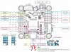
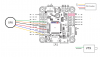
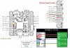
. Regarding where to hook it up on FC you can get 5V/GND basically anywhere on the board but check out the blue box on top right says PPM/SBUS think you want that one. DSM2 is a protocol used specifically by spektrum radios (think developed by navy).


Also yah don't need gps, the gps is completely optional the drone can fly with just accelerometer and gyro but I mean assumes you are the one managing throttle and making minor adjustments to keep it flying :D angle mode the quad will self correct to "level" or close to it so mostly hover on it's own or if flying with goggles would use acro mode (takes some practice in simulator to get used to that), line of sight I usually fly in angle mode so the quad self corrects to level. Only things GPS adds are return to home (go back to a location, roughly and land) or possibly some position hold, at least in betaflight. My plan is to put gps/compass on there then see if my FC supports iNav for trying out the GPS and waypoint control type things. Regarding the different colored wire I wouldn't be concerned with that probably same signal wire, almost always GND is black, power/V+ is red and what remains are signal wires typically.
 
Cool, thanks @wafflejock! Didn't know those servo cable were a std. thing, wasn't familiar with the term, I'll dig around and see if I can find one at home. As you say, will be easy to find otherwise. Regarding GPS. I got it because I want return to home, and as I have it I'll use it. More to come. Thx again.
 
While waiting for that servo cable I'm trying top get the GPS connected properly, which don't seem to be going that well. I tried soldering the wireas to the FCB according to the schema in that previous post. The GPS lights up and I think it might be getting satellites, as the leds are blinking green in all direction while the main led is permanently lit. Betaflight is however not lighting the icon for GPS in the top bar. I've tried to activate the different UARTS with 57600 bauds in the Ports settings and I've activated GPS in the Configuration page. It's crazy hard to find any reliable examples of connecting my GPS and FCB, not sure why that is. I've looked at all sorts of info but fall back to the Manual for the GPS. Can someone please have a look at the attached and let me know what you think? I need help figuring this out. Can the wiring possibly be as I've outlined it? I don't fully getb the TX, RX SDA, CLK, SCL things. Think the TX and RX is the signals, the numbers next to these the UART numbers, CLK and SDA might be the compass...SCL...is that the same as CLK? Confusing. Anyway, I need help! Thanks in advance!
 

Attachments

  • GPS signal issue.JPG
    GPS signal issue.JPG
    155.9 KB · Views: 1
Last edited:
Back
Top