Transmitter/receiver trouble

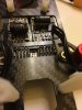
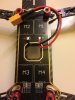
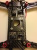
It looks like the dys has its esc mounted as part of the lower frame area. They were getting power from the CC3D. So now I have to attempt to put in a separate PDB? Well I think that this quad is going to get thrown and start with a fresh frame if that's the case.

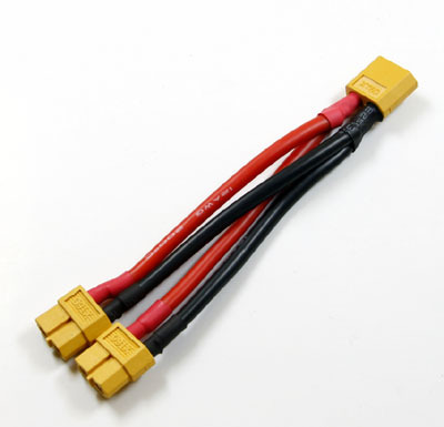
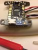
Well you don't necessarily need a seperate PDB. I've seen 'em with multiple jumper sets running to the ESCs in this instance. And since that FC does not require a step down in voltage, you don't need a PDB for that purpose. Hears an example, but you would need one more lead for your FC..............

wiring-harness-quadcopter-power-distribution-large.jpg
 
I was going to wire the servo wiring directly to the KISS FC board and have the installed ESC's do what they do or am I wrong as to how that should work.
 
Yeah, I forgot about those "built in" ESCs. Anyway, if you look at that diagram I posted for you, you'll not that there are three wires that run from an ESC to your FC. And there are 2 heavy wires that fun from your battery to the same ESC.
 
I saw that, but the built in ESC's don't have the connection for the heavy power wires.
Is there a connection on the quad itself for a couple of wires or a connector?? My big quad is definitely different..........but it has a PDB built into the lower frame board that provides direct battery power to the ESCs..........
 
Yes it had a main battery connector that is wired into the bottom of the quad that supplies power to the entire unit. It is actually located on the bottom panel where the ESC's are located.
 
This is the bottom of the dys 250 frame.
Ok, that's the mainline power for your ESCs and motors. So you need a two into one jumper so you can connect that connector and the connector from your FC to a single battery. Something like this...............
10cm-font-b-XT60-b-font-Connector-1-Male-2-Female-font-b-12AWG-b-font.jpg
 
Or you could solder two wires to those on the quad and just run them to the solder points on your FC. Myself I would go with the two into one connector...........
 
So maybe that's what the issue was when the CC3D was attached. That may be why the FC would not see the TX when I was attempting to do a set up on the computer.
 
This is the top side of the quad. I have already removed the upper frame panel to get to the FC.
 

Attachments

  • IMG_1759.JPG
    IMG_1759.JPG
    790.7 KB · Views: 2
Ok, then you could solder a couple wires to the ones already on there(the bottom side) and run them up thru that hole and then solder them to your FC. That would definitely be less weight and a cleaner look...............

And I noticed that the ESCs have numbering (M1, M2 etc) and I believe that it matches the layout for that Kiss FC. Just remember that your FC has a "forward" and it needs to point between M1 and M2....................

OH, if you do the solder in a pair of wires for power, be sure to leave a little slack as two of your ESC wire sets will solder on the bottom of your FC and two on the top of your FC.
 
What I've done so far is remove the servo jumper wires and cut one end off to hard wire it to the KISS FC. There is a Power and Ground pin that I'm going to have to connect also. The original CC3D FC used one of the servo wires from the main board to power the FC.
 
Here is a picture of the power and ground points that I'm going to have to wire in. Looks like it's another trip to the hobby store tomorrow for a few more items. I was there today for plugs for wiring in some lights.
 

Attachments

  • image.jpg
    image.jpg
    905.6 KB · Views: 6
What I've done so far is remove the servo jumper wires and cut one end off to hard wire it to the KISS FC. There is a Power and Ground pin that I'm going to have to connect also. The original CC3D FC used one of the servo wires from the main board to power the FC.

Are you talking about to power the FC??
 
Back
Top